Convection is a heat transfer process in which a fluid comes in contact with a warmer surface and removes heat from it. When external means such as pumps or fans are utilized to increase the flow rate, it’s called “forced convection.”
This process is widely applied in the cooling of electronics systems. It can be beneficial especially when the heat flux is up to 100 W/cm2.
This article will analyze forced convection and the following topics relevant to its application:
- Key characteristic of heatsinks utilized in forced convection
- How to choose the right fan for the heatsink
- Fans in parallel or series
- Conclusion
1- Key characteristic of heatsinks employed in forced convection
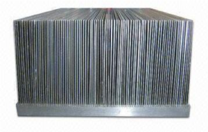
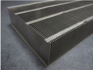
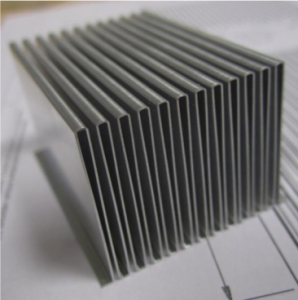
To maximize heat transfer with convection, it’s beneficial to increase the free surface available for the heat transfer. For this reason, heatsinks are usually designed with structures called “fins”.
Air speed is high due to the forced convection, and so it makes sense to use a very small gap between fins.
Different technologies can be applied to realize heatsinks with reduced fin spacing. With CAB brazing technology, it’s possible to obtain cost-effective heatsinks where the gap and position of the fins are engineered to optimize the cooling system’s thermal performance.
The following figures show heatsinks realized with CAB technology.


2- How to choose the right fan for the heatsink
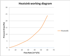
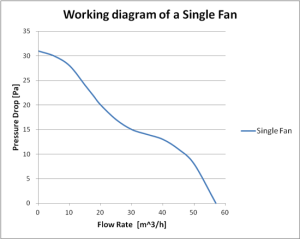
The first step in determining the right fan for the heatsink is to plot the pressure drop across the fins versus flow rate of the inlet fluid (see figure 4).
A fan generates pressure that moves air (or gases) to a resistance. To describe its performance, a curve is drawn where the resistance achieved as pressure drops are plotted as dependent on the flow rate (see figure 5).
In the graph, the hatched area represents the conditions under which the fan achieves better performance. To understand if the fan can be used with the engineered heatsink, we must see if the heatsink curve falls within the hatched area in the fan’s graph (see figure).
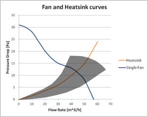
The working point is the point where the two lines intersect. So to maximize performance of the cooling system, it’s necessary to calibrate the fan with the indicated flow rate.
3- Fan in parallel or in series
We can use two or more fans to increase performance. Depending on their mutual position, two systems with the following characteristics are possible:
– PARALLEL:
– the total flow rate will be the amount of the single fan’s flow rate
– the total pressure drop remains the same
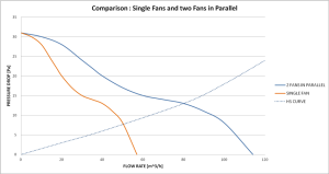
Figure 7
– SERIES:
– the total flow rate remains the same
– the total pressure drop will be the amount of the single fan’s pressure drop
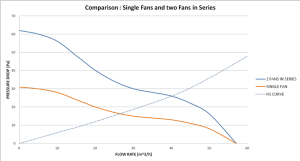
The graphs above show that the working zone changes as well. The parallel system can be useful when a higher air speed is required. The series system is advantageous in cases where the heatsink creates a high resistance (i.e. once with very close fins).
Conclusion
When an electronic device generates a heat flux higher than 70 W/cm2, natural convection is no longer sufficient, and a forced convection system is required. This type of system requires an additional power supply for the fans. Moreover, the final size of the complete system — including the heatsink and fan — is usually an important consideration.
To maximize thermal performance by minimizing the undesired feature described above, good engineering can transform a working system into an efficient one.
Click on the picture and download our free e-book
“Four Common Mistakes To Avoid When Selecting a Heat Sink”