In this article, the main aspects of liquid cooling system will be analysed with a special attention to the liquid cold plate (LCP) — the mechanical part responsible for the direct cooling of electrical devices.
Composition of a liquid cooling system
The basic liquid cooling circuit consists of:

The liquid cold plateis the mechanical component of the circuit where the electronic device is applied. This part is responsible for the heat transfer from the electronic device to the liquid.
Of course, the temperature of the liquid exiting the LCP is higher than the temperature of the liquid as it enters. In order to cool the fluid, a heat exchangeris utilized. Then a tank that functions as a reservoiris used to store the system fluid and ensure consistent bulk flow to the pump.
Finally the pumpgenerates the fluid movement, guaranteeing the flow rate needed to achieve the required LCP performance against the pressure drop of the entire system.
Liquid Cold Plate (LCP)
The liquid cold plate (LCP) is the component directly connected to the electronic device. It plays two basic roles:
– mechanically sustain electronics
– cool the heat source
The LCP usually consists of a metal plate with a fluid channel underneath. Many different technologies and materials can be employed to produce LCPs. One of the most effective options with improved performance is the CAB brazing technology.
This technology allows the joining together of two aluminium parts, or an aluminium part and a stainless steel part, resulting in finished objects that perform extremely well both mechanically and thermally.
The LCP formed from two aluminium parts consists of a base where a channel is milled and a cover that is brazed onto it. The channel engineering is complex and must take into account many factors, including thermal performance, pressure drop, mechanical resistance against pressure, and metal corrosion.
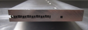
If the heat flux requirements are especially demanding, additional turbulators ensure even better performance.This structure offers uniform cooling of the modules footprint and high efficiency in heat exchange — even by low flow rate — due to local turbulence phenomena.

Figure 3: The turbolator and a section of an LPC with a turbolator brazed in the channel
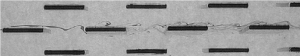
Figure 4: Effect of turbolators inside a flow path
Other options besides thealuminium-brazed LCP are the classic liquid cooler with copper embedded pipes, or an LCP with stainless steel pipes embedded or brazed. This last solution is usually appropriate when aggressive fluids are used or when fluid quality can’t be maintained.
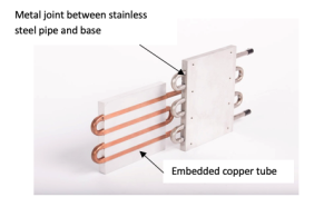
Figure 5: LCPs with pipes
Conclusions
The LCS is a complex solution that requires a non-negligible power supply to operate (pump, heat exchanger, digital controller, etc.). However, this is the only system suitable for meeting the high-heat flux demands of high-power electronics devices exceeding 150 W/cm2.
Thanks to advanced technologies such as CAB brazing — together with smart design engineering — it’s possible to find the best solution optimizing thermal performance and cost efficiency.
Click on the picture and download our free e-book
“Four Common Mistakes To Avoid When Selecting a Heat Sink”