To dispose of the heat produced by the dissipative phenomena (losses in the core + losses in the windings), it is necessary to use cooling systems that become more complex as the rated power of the transformer increases.
DRY TRANSFORMERS:
Powers up to a few tens of kVA.
The cooling is due to the natural or forced circulation (by fans) of the air.
TRANSFORMERS IN OIL:
The transformer is placed in a sheet metal case, filled with mineral oil, which acts both as an insulator and as a cooling fluid.
- To facilitate heat dissipation, the external wall of the body can be equipped with fins or cooling pipes (10-100 kVA);
- For powers between 50 and 500 kVA, external radiators cooled by natural convection are used;
- For higher powers, external heat exchangers are used, cooled by forced air or water convection
The various types of cooling are identified with abbreviations consisting of 2 or 4 letters that indicate the refrigerant fluids and the type of circulation
- A = air;
- O = oil;
- W = water;
- L = non-flammable insulating liquid;
- G = gas;
- N = natural circulation, due to convective motions of the refrigerant fluid;
- F = forced circulation by pumps or fans;
- D = forced and guided circulation;
For lower power transformers (up to a few kVA) the sections of the columns and the windings have a square shape.
For higher powers the windings have a circular shape:
- Shorter length of the coil;
- Greater resistance of electrodynamic efforts.
In this case, for the columns is adopted a stepped section which approximates the circular section.
For higher power transformers, in order to facilitate the heat dissipation, channels for the circulation of the refrigerant fluid are introduced

EXAMPLES OF WINDING SECTIONS
As regards dissipation for three-phase high power transformers, Priatherm has focused on liquid technology, with forced circulation by pump (WF).
The idea is to take advantage of the existing cooling channels, between core-winding and possibly between the various layers of windings, to insert it inside the liquid cold plate, in which to circulate a mixture of water and ethylene glycol.
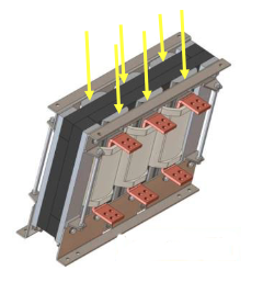
LCP BETWEEN WINDINGS AND CORES OF EVERY PHASE
In the previous versions of this product, it is obtained by deep drilling and subsequent insertion of a by-pass between the channels, welded to ensure the seal.
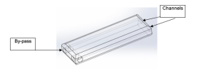
3D REPRESENTATION OF LCP OBTAINED BY DEEP DRILLING
For the current market, the innovation would be the production process and in particular the following phases:
1) The holes obtained directly from the extrusion process, eliminating an expensive, repetitive and critical machining process;
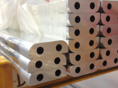
EXAMPLE OF CUSTOM EXTRUDED PROFILE FOR TRAFO-LCP
2) the by-pass between the IN and OUT channels, obtained with milling on the bottom and a brazed flat aluminum cover;

3D REPRESENTATION OF THE INTERNAL CIRCUIT
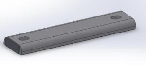
3D REPRESENTATION OF THE FINISHED PRODUCT
Click on the picture and download our free e-book
“Four Common Mistakes To Avoid When Selecting a Heat Sink”